TEST PRINCIPLE
Evaluating the elasticity of noodles using a noodle tensile fixture.
BACKGROUND
The noodle tensile fixture consists of lower and upper friction rollers that are knurled to ensure a firm grip.The rollers have a slot (orifice) through which the sample can be passed before winding the sample round each friction roller. The sample is wound two to three times onto each roller in order to anchor the sample ends. Samples can also be wound directly onto the friction rollers without using the orifice. The choice of method used must be consistent for every test performed. Before starting a test, the sample should be fully extended with no points of weakness along its length. A test is considered successful if the sample breaks along the extended part.
METHOD
Equipment:
| Instruments: |
CTX with 50Kg Loadcell |
| Accessory: |
TA-BT-KIT Fixture Base Table TA- NTF Noodle Tensile Fixture |
| Software: |
Texture Pro Software |
Settings:
| Test Type: |
Tension |
| Pre-Test Speed: |
1.0 mm/s |
| Test Speed: |
3.0 mm/s |
| Post-Test Speed: |
3.0 mm/s |
| Target Type: |
Distance |
| Target Value: |
40.0 mm |
| Trigger Force: |
5 g |
Note: Thicker samples may require a higher trigger load and a longer tension distance
SAMPLE PREPARATION
When preparing the sample, the noodles should be cooked under controlled conditions. The weight of dry noodles, volume of water used, cooking time, drainage time, and time period between cooking and testing must be kept constant for comparison purposes. For this application, 100g of noodles were placed into a microwavable dish containing 300 ml of boiling water. The noodles were cooked for 5 minutes in a 900W microwave. Samples were left to cool for 1 minute prior to testing.
In general, cooking times and the volume of water used will vary depending on sample size and weight.
PROCEDURE
- Place the lower friction roller on the base of the instrument and loosely tighten the T-bolts to enable some degree of mobility.
- Attach the upper roller to the probe shaft of the instrument.
- Lower the instrument arm until the upper friction roller is a few millimeters from the lower friction roller.
- Align the lower friction roller to the upper friction roller by re-positioning the lower roller.
- Once alignment is complete, lock the T-bolts on the lower roller to prevent any further movement.
- Raise the arm of the instrument to provide enough space to wind the sample.
- Pass the sample through the orifice on the upper friction roller and then wind the sample 2-3 times onto the roller. Tighten the screw on the upper friction roller to prevent further movement before repeating this procedure for the lower friction roller. The samples can also be wound onto the rollers without passing through the orifice.
- Raise the instrument arm to extend the sample.
Note: Always ensure that there are no apparent weaknesses along the length of the sample before performing a test as this may lower the tension forces and distance to break point values.
When testing different brands of noodles, the hardest sample is best tested first in order to anticipate the maximum testing range required. This will ensure that the force capacity covers the range for other samples being tested.
RESULTS
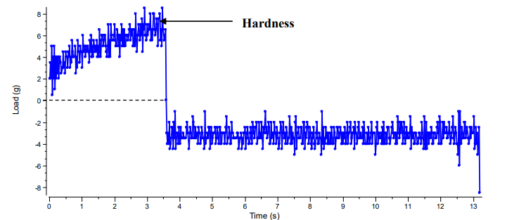
Figure I
Figure I A graph to show the extensibility of noodles using a noodle tensile fixture
The maximum peak force is a measure of sample hardness. This is the force required to break the sample.

Figure II
Figure II A load verses distance graph for the extensibility of noodles using a noodle tensile fixture
This is an alternative option for displaying the results. The graph shows similar features to the load/time graph but with an additional measurement. The load/distance graph can measure the distance to breaking point. This value can be used to compare the elasticity of samples. The longer the distance to breaking point, the more the elastic component of the sample.
Note: If only noodles are being tested and there is no requirement for any other type of pasta a 1000 g or even 100 g CT3 instrument may be used for this test
OBSERVATIONS
When a trigger load of 5 g has been attained, the upper tensile grip proceeds to stretch the noodle over a distance of 40 mm at a test speed of 3 mm/s. When the elastic limit of the noodle has been exceeded, the noodle snaps. This is observed as the maximum tension force on the graph (see fig. 1 and 2), the higher the force value; the greater the tensile strength of the sample. The elastic component of the sample can also be tested. From the load verses distance graph, the measured distance to break point is an indicator of sample elasticity; the greater the extension distance, the more elastic the sample.
The table below summarizes the average results from two samples:
| Sample |
Peak Load (g) |
Deformation at Peak Load (mm)
|
| Noodles |
8 ± 0.7 |
9.84 ± 0.97 |
>>Download PDF of this application note.