TEST PRINCIPLE
Evaluation of the peel strength of a foil on a yoghurt bottle using a general peeling jig (TA-GPJ).
BACKGROUND
Peel tests measure the adhesive or bond strength between two materials. Typical examples include packaging materials, laminated surface coatings, films, and backings amongst others. A peel test is performed when a tension load or force is applied to the materials under investigation in one of three ways as listed below:
(1) Pulling a flexible material away from a non-flexible material both of which are held vertically forming a 180 o peel.
(2) Pulling a flexible material (positioned vertically) away from a non-flexible material (positioned horizontally) to form a 90 o peel.
(3) Pulling two flexible materials axially from each other. This is known as the T peel test.
Although the peel test techniques listed above may require a variety of fixtures and test grips, the data analysis is the same requiring the averaging of the load values during the peeling over a defined time period. The test performed here is a 90o peel test using a general peeling jig (TA-GPJ). In preparation for the test, the flexible material (backing, film, etc) is inserted (or partially peeled prior to inserting) to the upper grip and the product (the non-flexible material from which the seal strength will be measured e.g., bottle) is attached to the fixture using the rubber holder and supported at its base by the adjustable screws. As the instrument arm drives the upper grip in the tensile direction, the seal is peeled away from the product. The force required to peel the flexible material from the product is a direct measurement of bond strength. In quality control, performing a peel test is important in order to assess the seal integrity and safety of the product. The tests also ensure the proper functioning of the adhesive seal (i.e., seal is tight enough to keep the product sterile or protected, yet easy enough to peel without causing spillages or inconsistencies in peel strength).
METHOD
Equipment:
| Instruments: |
CTX with 5kg Loadcell Instrument |
| Accessory: |
TA-GPJ- General Peeling Jig |
| Software: |
Texture Pro Software |
Settings:
| Test Type: |
Tension |
| Pre-Test Speed: |
1.0 mm/s |
| Test Speed: |
1.0 mm/s |
| Post-Test Speed: |
1.0 mm/s |
| Target Type: |
Distance |
| Target Value: |
32.0 mm |
| Trigger Force: |
5 g |
SAMPLE PREPARATION
Condition samples to the temperature testing conditions.
PROCEDURE
- Attach the probe shaft connector to the instrument
- Slide the fixture nut and spring into the slot at the base of the instrument and move it towards the centre of the base of the instrument.
- Likewise, slide the universal peel rig into the slot at the base of the instrument and move the fixture towards the centre of the base of the instrument.
Note: The position of the general peeling jig and fixture nut and spring depends on the inclination angle of the platform. Hence for a 0-degree angle, the fixture is positioned towards the centre of the instrument base whereas a 45- and 90-degree peel test would require the fixture to be positioned further down the base of the instrument. These positions ensure that the string connecting the grips (now clamping the sample) to the probe shaft connector is parallel and not slanted.
- Raise the support plate of the fixture using the screws at the back of the fixture. This will provide room to lock the fixture into position.
- Align the orifice of the general peel fixture with that of the fixture nut and spring.
- Using the screw and Allen key provided, lock the general peel fixture into position.
- Place the sample on the support plate and using the small screws at the front of the fixture clamp the sample.
- Partially peel the protective cover and insert this loose end into the grip and tighten using the screws. Ensure that the protective cover is inserted over the full length of the grips. This will ensure a tight grip.
- Lower the instrument arm so that the grip can be connected via the thread to the probe shaft connector.
- Wind the thread of the grip round the screw of the probe shaft connector and tighten using the screw.
- Raise the instrument arm by 1 mm increments until the protective cover and the grips and thread are held upright and perpendicular to the rim of the bottle with no slack on the thread.
- Commence the test
RESULTS
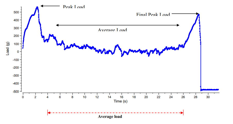
Figure I
Figure I The peel strength of a seal from a yoghurt bottle using a general peeling jig (TA-GPJ)
The two peak values seen on the graph are a measure of the force required to break the rim-seal contact at the start of peeling and at the end of the peeling. The plateau on the graph is the force required to continue peeling and is calculated as the average load (in this case calculated within the time scale of 4 seconds to 26 seconds). Large fluctuations on the graph would indicate inconsistencies in the peel strength.
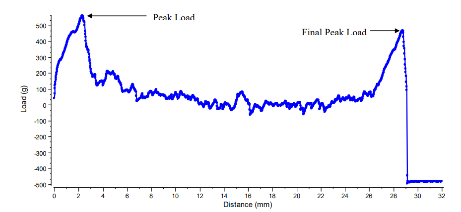
Figure II
Figure II The load verses distance for the peel strength of a seal from a yoghurt bottle.
This graph shows the peak load and final load as well as the distance traveled throughout the peeling process.
OBSERVATIONS
When a force of 5 g has been attained in the tensile direction, the grips proceeds to pull the bottle’s protective cover and the force is seen to rapidly rise as the bond strength of the seal between the rim of the bottle and cover resists the applied force. When the tension load exceeds the bond strength of the seal, the peeling begins. This is shown as the first peak on the graph and by the sudden drop in load values. As the peeling continues, the graph plateaus. This region of the graph represents the force required to continue peeling. As the final section of the seal is peeled off, the tension load rises to form a second peak followed by a drop off in load values as the lid is completely separated from the bottle. This second peak represents the force required to separate the cover from the rim of the bottle.
A peel test will indicate potential problems that may arise from the seal quality and can therefore be used to optimize seal strength. Where the peak force is very high at the start of the test followed by a rapid drop in force may indicate the possibility of spillages of low viscous products as the user attempts to peel off the seal from a lid. Moreover, large fluctuations in the force to continue peeling will also indicate poor seal quality with inconsistencies in peel strength and spillages also likely to occur. The advantage of this peel test is that it can be extended to all types of rectangular, oval, and circular containers and is quick to perform.
The table below Summarises the results:
| Sample |
Peak Load (g) |
Average Load (g) |
Work Done (mJ)
|
| Bottle Cover |
561 |
35.7 |
14.43 |
>>Download PDF of this application note.